Tuesday, December 25, 2018

Got latency issues with Samplerbox?

If you are wondering what is wrong with the latency issues in you Samplerbox build, follow this easy 1-step tutorial:

1) Stop using the "1GrandPiano" sample set.

Just look at this:

Sound of silence

The samples in the "1GrandPiano" set have varying lengths of silence before the sample starts. The silence is often just 10ms but on some samples it is up to 50ms.

If you have fought with latency issues before, you know that 50ms is a lot. It will make playing really hard. But what's even worse than a stable 50ms latency is that these samples have different lengths of silence before them. That makes the latency seem random and is really awful to play.

This sample set was one of the first introduced on the Samplerbox site. I think it was there from the beginning. So when I read complaints about latency with Samplerbox, I get the feeling that the cause is actually this sample set in most cases.

If you really want to use this sample set, you could trim the silence out of the samples. Some years ago I made a python script to do just this.

Disclaimer: I was just learning python at the time, so the code is probably not very pythonic. But it worked for me.

Note that it will cut silence and also a part of the attack! The higher the threshold value, the more you will cut from the beginning of the sample.

It will also cut any silence after the sample. That will make the sample set much smaller and thus faster to load.

Have fun.


# Sample trimmer for Python 3.x
# by Juho-Eric
# 24.10.2016
#
# This script trims silence out from the beginning of wave files.
# It makes them respond better when played live (reduces latency) and
# makes the file size smaller by removing the unnecessary silence.
#
# The script looks for .wav files in this directory and creates
# a subdirectory "trimmed" that contains the trimmed version of each
# sample.
#
import glob
import os
import wave
import struct
import timeit

def getframe(frames, i):
    framelong = frames[4*i]+(frames[4*i+1]<<8)+(frames[4*i+2]<<16)+(frames[4*i+3]<<24)
    framebs = struct.pack('L', framelong)
    return struct.unpack("<hh",framebs)

def setframe(frames, f, l, r):
    framebs = struct.pack('<hh', int(l), int(r))
    a,b,c,d = struct.unpack('BBBB',framebs)
    frames[f*4] = a
    frames[f*4+1] = b
    frames[f*4+2] = c
    frames[f*4+3] = d
    return 

# Just for checking how much time it takes to run
scriptstart = timeit.default_timer()

startthreshold = 100
endthreshold = 10
fadeinlength = 4
fadeoutlength = 4
wavefiles = glob.glob("*.wav")

totalcutframes = 0
totalcutsecs = 0

# Make output directory if not made yet
try:
    os.stat("trimmed")
except:
    os.mkdir("trimmed")
    
# Go through all wave files in this directory
for file in wavefiles:
    win = wave.open(file, 'r')
    params = win.getparams()
    #nbits = win.getsampwidth()*8
    #nchannels = win.getnchannels()
    nframes = win.getnframes()
    framerate = win.getframerate()

    # File is opened for reading.
    #print("Opening "+file+": "+str(nchannels)+" channels "+str(nbits)+"-bit "+str(framerate)+" Hz")
    
    # Get all frames as bytearray.
    frames = bytearray(win.readframes(nframes))

    # Find the first point where threshold is broken (trim starting silence)
    framewas = 0
    for i in range(nframes-1):
        l,r = getframe(frames, i)
        if (abs(l) > startthreshold or abs(r) > startthreshold):
            framewas = i
            break
    
    startframe = framewas
    startsecs = startframe / framerate
    totalcutsecs += startsecs
    totalcutframes += startframe
    print(file +" cut from start "+str(startframe)+" frames / "+str(startsecs)+" s")
    
    # Find the frame where the silence starts again (trim ending silence)
    framewas = nframes
    for i in range(nframes-1, 0, -1):
        l,r = getframe(frames, i)
        if (abs(l) > endthreshold or abs(r) > endthreshold):
            framewas = i
            break
    
    endframe = framewas
    cutendframes = nframes - endframe
    cutendsecs = cutendframes / framerate
    totalcutsecs += cutendsecs
    totalcutframes += cutendframes
    print(file+" cut from end "+str(cutendframes)+" frames / "+str(cutendsecs)+" s")
    
    # Create fadein
    for i,f in enumerate(range(startframe,startframe+fadeinlength)):
        l,r = getframe(frames,f)
        multiplier = ((i+1)/(fadeinlength+1))
        setframe(frames, f, l*multiplier, r*multiplier)
    
    # Create fadeout
    for i,f in enumerate(range(endframe-fadeoutlength,endframe)):
        l,r = getframe(frames,f)
        multiplier = ((fadeoutlength-i)/(fadeoutlength+1))
        setframe(frames, f, l*multiplier, r*multiplier)
    
    # write output file
    wout = wave.open("trimmed/"+file, 'w')
    wout.setparams(params)
    wout.writeframes(frames[startframe*4:endframe*4])
    wout.close()
    win.close()
    
print("Total: cut "+str(totalcutframes)+" frames / "+str(totalcutsecs)+" s")

scriptstop = timeit.default_timer()
print("Operation took "+str(scriptstop-scriptstart)+" seconds")

Saturday, December 20, 2014

DIY headphone distribution amplifier

Sometime back in 2007 I was in need of a headphone distribution amp. I couldn't find a device for any reasonable price, so I had to make one myself.


The completed headphone amp in 2007

Then I happened to find the PAiA 9206K Headphone Distribution Amp. At the time I couldn't afford to buy it, but I was in luck as PAiA provides schematics for their devices. I love it when companies do that!

So I sourced the parts and built it myself. Now I owe PAiA one! I'll keep them in mind when it's time to start building my modular...

Insides with the op amps and pots soldered. Input and output jacks are still missing.

The schematic is very simple, and you can easily see how to add/remove channels if needed. The PAiA kit has 6 headphone outputs, but I needed only 4.

Use low-noise op amps that work with a supply of +6/-6 volts. Unfortunately I don't remember what op amps I used... They might have been TL072. Using a dual op amp makes for 1 op amp per stereo headphone channel.

The insides completed. Not very pretty wiring, but it works just fine!

Fitting it in, almost ready.

Now only missing some paint...

For the project case I used an old speaker. When painting it I tried to do some stencil work but that failed miserably as you can see...


The device works and is in use to this day. Thanks to PAiA!

Wednesday, December 10, 2014

Python3 TCP server for Windows 7 remote control

I did a quick and dirty volume remote control for my Win7 PC and decided to share it.

The script opens a TCP server on the machine, and listens for connections. When a client connects, it will react to commands 'U' (volume up), 'D' (volume down) and 'M' (toggle mute).

It works at least with Python 3.4 and it uses NirCmd to set the Windows master volume. I first looked at pywin32 library for the volume control, but I couldn't find any good documentation, so I went the easier route and decided to use NirCmd instead.

It might not be the prettiest solution, but it works for me!

Place the below code into a .py file, for example 'rcserver.py' and run it with Python 3.4. Also place nircmd.exe in the same directory.

You can try it out by using PuTTy and connecting to 127.0.0.1 port 5005 with 'Raw' connection type. Then enter M, D, U and your computer's volume will change.

I'm using a Raspberry Pi to control it with netcat. Here's how:

Install netcat if you don't have it:
apt-get update
apt-get install netcat 

Send mute command:
echo -n "M" | nc -q1 ip.address.of.computer 5005 
This echoes a M character to the IP address on port 5005, and quits after one second.
Replace the IP address here and in the Python code with your Windows computer's LAN address.

Note that you can remote control almost anything by adding commands to the script.

Here is the code:


 # Python 3 server for Windows 7 remote control   
 # Juho-Eric 11. Dec 2014  
 #  
 # You need the following to run this:  
 #  
 # Python 3.4  
 # https://www.python.org/  
 #  
 # NirCmd  
 # http://www.nirsoft.net/utils/nircmd.html  
 #  
 # Place nircmd.exe in the same directory as this script.  
   
 import socket  
 import subprocess  
   
 #Parameters for TCP server.   
 TCP_IP = '127.0.0.1'  
 TCP_PORT = 5005  
 BUFFER_SIZE = 20  
   
 #This code is to hide the command prompt window when running nircmd.exe  
 si = subprocess.STARTUPINFO()  
 si.dwFlags |= subprocess.STARTF_USESHOWWINDOW  
 #si.wShowWindow = subprocess.SW_HIDE # default  
   
 #Create the TCP server socket  
 s = socket.socket(socket.AF_INET, socket.SOCK_STREAM)  
 s.bind((TCP_IP, TCP_PORT))  
 s.listen(1)  
   
 #Main loop, this will loop on each connection  
 while 1:  
   conn, addr = s.accept() #get new connection  
   print('Connection address:', addr)  
   while 1: #This will loop on each command received  
     data = conn.recv(BUFFER_SIZE) #receive data  
     if not data: break #check if connection closed  
     print("received data:", data)  
     if data == b'U':   
       print('volume up')  
       subprocess.call('nircmd.exe changesysvolume 1000', startupinfo=si) #increase volume 
       subprocess.call('nircmd.exe mutesysvolume 0', startupinfo=si) #remove mute  
     elif data == b'D':  
       print('volume down')  
       subprocess.call('nircmd.exe changesysvolume -1000', startupinfo=si) #decrease volume
       subprocess.call('nircmd.exe mutesysvolume 0', startupinfo=si) #remove mute  
     elif data == b'M':  
       print('mute toggle')  
       subprocess.call('nircmd.exe mutesysvolume 2', startupinfo=si) #toggle mute  
   conn.close() #close the connection  
   print("connection closed")  
   

Saturday, April 26, 2014

Mesa Boogie F-50 footswitch schematic

I'm repairing a Mesa Boogie F-50 footswitch, and made a schematic of it.


Here it is if anyone needs it.

Schematic of the Mesa F-50 foot pedal


The pedal has three switches: channel, contour and reverb.


The connector is a 5-pin female DIN, similar to MIDI connectors.

Ferrofish B4000+ AND HOW I FUCKED IT UP


 NOOOOOOOOOOOOOOOOOOOOOOOOOOOOOOOOOOOOOO!!!!!!!!!!!!!!!!!!!!!!!!!!!


FUUUUUUUUUUUUUUUUUUCK!!!!!!!!!!!!!

Saturday, February 23, 2013

Roomba accident

Have a Roomba at the office. Go to work and find this:


Friday, July 6, 2012

Backing up Nord Lead 2 patches

Hi there.

After a long pause in posting, here's a guide for backing up Nord Lead 2 patches.


What you need for this:
 - Clavia Nord Lead 2 (of course)
 - A computer running Windows
 - A USB-MIDI interface or a sound card with MIDI
 - A MIDI cable
 - MIDI-OX software (free download link)

MIDI-OX is a great tool for synth players. You can do all sorts of MIDI tricks with it, including backing up your sounds on your PC. The software is freeware for non-commercial use.

Nord Lead and other synthesizers often have the ability to export the patches through MIDI as "SysEx dumps". SysEx stands for system exclusive data. MIDI-OX can receive this data and save it as .syx files.


Walkthrough of a complete backup

First, install MIDI-OX and start it up. Connect MIDI IN of your PC's MIDI interface to the MIDI OUT of the Nord Lead 2.

In order to receive a sysex dump on the MIDI-OX, click View --> SysEx...
This opens the SysEx View and Scratchpad. Then click on Sysex --> Receive Manual Dump...
A message box appears, asking you to wait for the dump to complete.


Now you need to send the SysEx data from Nord Lead 2. After each dump, click on the "done" button. You can then save the dump by clicking Display Window --> Save as... 

Here's what to do on the Nord Lead 2:

How to dump programs
Be sure that you are in manual mode and then press SHIFT - DUMP ALL.

Manual mode looks something like this...

How to dump performances
Nord Lead 2 performances are stored on ROM and cannot be edited. Thus it's not necessary to back them up. However, here's how to do it: Press performance to get in performance mode and then press SHIFT - DUMP ALL.

Performance mode.

Backing up your PCMCIA Sound Card


If you have a Nord Lead 2 Sound Card, chances are that it's battery is running dangerously low by now. The battery life is around 10 years, give or take. You can replace the battery without data loss if you do it quickly. But if you want to be sure no data is lost, it's best to back it up first.

Here's how to back up the data:

How to dump program banks 1-3 from PCMCIA card:
 - Be sure that you are in manual mode (not performance mode).
 - Press up key until you have "1." on the left of the LCD display.
 - You now have bank 1 of the card selected.
 - Press SHIFT - DUMP ALL.
 - Repeat this for banks "2." and "3."

Bank 1 from the sound card selected, patch #9.

How to dump performances from PCMCIA card:
 - Press performance to get in performance mode.
 - Press up until you get "1." on the left of the LCD display.
 - Press SHIFT - DUMP ALL.


Restoring backups

You can restore any bank you've dumped easily. You need a connection between the MIDI OUT of your PC and the MIDI IN of the synth.
Just open the Sysex view and select File --> Send Sysex File... 
The bank you have selected on the Nord Lead 2 will be overwritten.


Single program / performance dumps

Doing single program or performance dumps is a lot of help when creating variants. To do a single patch dump, just press SHIFT + DUMP ONE.


Sharing your sounds

When you've done with backing up your precious patches, why not share them with the world?

Electro-music has TONS of Nord Lead 2 patches for you to try out. However, they seem to only archive single patches.

Another great place for browsing sharing sysex data is Sysexdb. There's no Nord Lead 2 data in there yet though. That's why you should send yours there too!

Sunday, March 25, 2012

Modifying a chinese wall wart for use in Europe

I ordered a USB hard drive case from Dealextreme some time ago, and forgot to check if it has a wall wart compatible with the finnish wall sockets. So of course I got some chinese wall wart with no way of plugging it in anywhere.

Luckily, it accepts the 230V 50Hz AC, it just doesn't physically fit in the socket...

One option would be to buy an adapter, but I couldn't find anything less than 35 euro. Also, even if I found some cheap adapter, it would probably cause power problems to the hard drive case, making the hard drive unstable. So I soldered an europlug cord on the wall wart.


The adapter and the cord, soon to be one.


If you do something like this, please don't have it connected to the wall when you're working on it. At least please don't sue me if some fucking idiot dies like this.

You need some heat shrink tube and a heat gun for this one, to hide the mains voltage connectors totally. You want to make this thing safe you know. If you don't have a heat gun, a hair dryer or a lighter might do.

Soldered together, with heat shrink tubing.

Heat shrink tubes in place.

After applying the heat gun.


A HUGE piece of heat shrink tubing...

At this point I learned that indeed, heat shrink tube shrinks. Especially with bigger tubes, you need to leave some extra length, because it will shrink also in length...

Didn't go as planned...


Fortunately, the heat shrink I had at hand fit over the europlug, so I didn't have to start all over. I put a bigger piece of heat shrink on top of the old one and used the heat gun again...

Even bigger piece of heat shrink. This should do it.

...and there we go. Works nicely and safe too!

Finally, ready for use!

Braun 1508 shaver battery replacement

This one might gross someone, but I don't give a f--k. If you're offended by imagery of decade-old greasy hairs - of dubious origin - go watch the disney channel.

I don't really use my Braun 1508 shaver that much, I prefer the 3-blade, but sometimes it's a lot of help when trimming the face in a hurry. I've had this shaver for over 10 years, and it's still working nicely for me - but the battery is now long gone. I've just used it plugged to the wall for like 6 years.


Finally, I decided to change the battery. It's just a 1.2V NiMH cell, you can get a new one from literally any grocery store. Here's a guide of how I did it.

First, TAKE OFF THE POWER CORD and keep it that way while working or you'll cease to exist. Then get the screen off and open the two screws on the side.

Open these screws...

After unscrewing them, you have to use some force to get the cover open. There's this white plastic locking mechanism with a spring in it, and that might break. My spring flew somewhere, and I couldn't find it, so in the end I just threw away the white piece of plastic and glued the shawer back together...

The 1580 opened up.

A view of the electronics.


This is the + side of the cell. Remember this. It's important.


...and the negative electrode is connected here.


I took away the cell with some cutters and a bit of force. It's glued in place.

Old cell ripped off the PCB, and the replacement cell.

Then I soldered some wires on the battery. Batteries shouldn't really be soldered on, since the heat will not do them good. But you probably don't have a spot welder at hand. Just use a soldering iron at maximum power and be fast, and it will be fine. The electrical connection doesn't have to be perfect, since it's a low-power circuit.


Wire soldered to the replacement Varta cell - negative electrode.
When soldering don't block the small vents on the positive electrode. They are there to release gas if the cell it overcharged. If they are blocked, the gas will build up and might result in an explosion when charging.

The positive side. Don't block the vents on the cap.

Then solder the wires to the PCB where the original cell was connected. Remember to solder it in the correct polarity, the same way as the original cell.


+ side

The - side.

That's it. Just put the thing back together and the shaver's like new! OK, maybe not brand new, but still, working.

It doesn't really make sense that you need to buy a new shaver when the battery dies. I quess it's partly a safety issue that they don't put a battery slot in the shaver, since it also has mains voltage inside... But mostly it must be the increased shaver sales they get due to dead batteries. So if you have any soldering skills, just fix the thing yourself. You'll prevent generating unnecessary e-waste and save some money from the greedy fingers of Braun.

F--k you Braun, I win.

Thursday, December 8, 2011

LTSpice simulation of Chua's circuit

[EDIT 2012-03-25: fixed a stupid error on the sample rate]


From time to time I get spam from Farnell (a component distributor), and on their newsletter they're promoting a free webinar by Elektor magazine, titled "Let's Build a Chaos Generator!". The event is due 15th of December at 6:00 PM EET, so if you have nothing better to do, that's one good way to waste your time.

I had been reading on chaos generators in the past, and this e-mail got me interested again. Their design is somewhat complicated, with a total of 13 stages of 7 different circuit blocks. You can read all about it in the PDF they published.

Elektor's Chaos Generator won't fit in your pocket.

A much simpler chaos generator that can be built with a lot less components is called Chua's circuit. The downside with this simple circuit is that you need an inductor which you might have to wind up yourself. Also there should be much less variety than in the waveforms of the Elektor circuit. It has so many stages that can saturate to give different waveforms.

Still, Chua's circuit is very interesting to fiddle with. I haven't built the circuit yet, but I did some simulations with LTSpice IV and here's what I found out.

First, I googled for schematics. The first result was this great page giving me a nice schematic and details on the circuit. Another page I found had a quite similar circuit but with a little bit different component values. I built a circuit with LTSpice based those two pages.

My LTSpice version of Chua's circuit.

If you want to try simulating the circuit yourself, click here to download the .asc file.

The circuit is powered by two 9V sources, one positive and one negative. Would be nice to see a single-supply version by the way! There are two outputs, nodes V1 and V2. I chose the LT1351 op amp, since it should be quite near the common TL071 series op amps, and the model comes ready with the LTSpice installation.

The circuit can be tweaked by varying R6 from 0 to 2k. Somewhere in between lies chaos. I found 1.6kohms a good value.

A transient simulation to 1/10th of a second gives the following waveforms for V1 and V2:


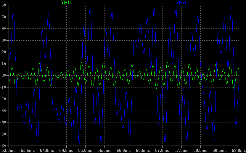
From up here, voltage V2 (blue) seems to be bouncing around two different DC levels at the same time!

A closer zoom on the waveforms shows some detail:


And if we change the x-axis to be V2 and the y-axis to V1, we get the beautiful double scroll plot:


I also ran an FFT for the signals, to see what kind of frequencies are involved:


Hmm, seems like it's audible... and so I couldn't stop there. I wanted to hear what it sounds like, so I made a simulation which outputs .WAV files.

Since LTSpice IV clips WAV outputs with an amplitude over 1V, I had to attenuate the two signals with voltage dividers. Here's the LTSpice circuit I used:

LTSpice simulation with WAV output!

If you want to simulate this one yourself, download the LTSpice project here.

The simulation for 10 seconds of audio took some time with my settings, and generated 500MB of raw data. Looking at it now, the time step (0.1ms) is lower than the sampling time... You might want to simulate with approximately 1/44100 time step, but that will produce even more data.

After all this, I could finally listen to the horrible screeching noise of chaos.

And so can you: The signal V1 (.wav) is more high-pitched, while the V2 (.wav) has lower frequencies in it's spectrum (like you can see from the FFT).

What it sounds like is noise, and a very annoying kind of noise.

I don't know yet how changing the value of R6 realtime will affect the sound. For that I would need to build the circuit and try it. With low values of R6, the circuit oscillates with a constant frequency. It would be neat to hear the moments at the edge of chaos. So I'll be probably building this one sometime. If someone has already built it, go ahead and post a comment!

Tuesday, September 27, 2011

Kärmes


When walking home from the uni today, I found this dying snake on the road. I quess it was hit by some car, or the cold finnish autumn had taken it's toll on it...

After taking some pictures, I left it to die in peace.

Kyynel!

Tuesday, September 13, 2011

Portable speaker for MP3 player

I made this portable speaker in the summer. It mixes the stereo input into a mono signal, which is then amplified. It's powered by a six pack of AA batteries. The batteries are held in an external battery pack, so they are easy to change on the fly, without the need of a screwdriver.

Completed speaker pumpin' out some bass

I was going to a cabin with the guys to celebrate juhannus (midsummer) the next day, and there was going to be no electricity. Juhannus without music wasn't an option, and I'm not too impressed by the portable speakers available in stores (overpriced and shit sound). So I built my own blaster that evening.

The circuit is a modified version of the portable guitar amplifier I've built many times. I found the original circuit years ago from the great site Red circuit designs. The circuit is modified to have a simple stereo-to-mono mixer in the input, consisting of resistors R1 and R2. I chose 1k as their value, that should be enough to isolate the left and right channels from each other, since the headphone output on an MP3 player has a low impedance.

There is no volume control, instead I just use the volume control of the MP3 player. If someone wants to add one, just replace R3 with a potentiometer and connect "In+" of the TDA7052 to the middle pin of the potentiometer...

Schematic of the amplifier.

Going through my sizeable e-trash collection I found an old pairless computer speaker. It would get a new life soon.

The victim, a pairless computer speaker.
It was a left speaker, with just a speaker inside and an RCA jack on the back. I was going to use that as the power jack.

An RCA jack on the back was going to be the power input.

I took the metal leg off to access the screws and opened the case. Next I cut the wires off the speaker. There was some foam padding inside, which I removed for a while.

Case opened and wires cut.

I soldered all the amplifier circuit on a small piece of stripboard and then the speaker and the jacks. A single screw hole in the back of the case was used to fasten the thing there.

The amplifier circuit board is fastened to the wall with a screw.

I glued some mouse pad pieces to the most critical places to ensure there's no unwanted vibrations. To top it off I put back the original foam padding.

Some pieces of old mouse pads ensure the wires don't vibrate around.

I put also the original foam padding back to further eliminate vibrations.

Here is the backside of the finished speaker. I sticked an inspirational sticker on the back. The RCA jack on the left is for power and the 3.5mm jack is a stereo line input.

Connectors on the back.

I used some part of an old projector as a vise when gluing the battery pack together. Very handy. Another gem saved from the trash.

Gluing the battery pack together...

The power packs are also 100% recycled: the battery holders and the piece of RCA wire were also found in e-trash.

Finished test battery pack, with random AA's I had at hand.

The speaker was a hit in Juhannus and got very good feedback from it's bassy and clean sound. Just have enough batteries with you - it ate 3 six-packs of AAs during the 3-day trip and would have eaten even more. Of course, the speaker was on all the time. When the batteries are running low the sound starts to get distorted but turning down the volume a bit helps. This way you can also extend the battery life a bit.

That's all folks!

Links
Red free circuit designs -  Mini Portable Guitar Amplifier
My mini guitar amplifier build