Showing posts with label analog. Show all posts

Saturday, December 20, 2014

DIY headphone distribution amplifier

Sometime back in 2007 I was in need of a headphone distribution amp. I couldn't find a device for any reasonable price, so I had to make one myself.


The completed headphone amp in 2007

Then I happened to find the PAiA 9206K Headphone Distribution Amp. At the time I couldn't afford to buy it, but I was in luck as PAiA provides schematics for their devices. I love it when companies do that!

So I sourced the parts and built it myself. Now I owe PAiA one! I'll keep them in mind when it's time to start building my modular...

Insides with the op amps and pots soldered. Input and output jacks are still missing.

The schematic is very simple, and you can easily see how to add/remove channels if needed. The PAiA kit has 6 headphone outputs, but I needed only 4.

Use low-noise op amps that work with a supply of +6/-6 volts. Unfortunately I don't remember what op amps I used... They might have been TL072. Using a dual op amp makes for 1 op amp per stereo headphone channel.

The insides completed. Not very pretty wiring, but it works just fine!

Fitting it in, almost ready.

Now only missing some paint...

For the project case I used an old speaker. When painting it I tried to do some stencil work but that failed miserably as you can see...


The device works and is in use to this day. Thanks to PAiA!

Thursday, December 8, 2011

LTSpice simulation of Chua's circuit

[EDIT 2012-03-25: fixed a stupid error on the sample rate]


From time to time I get spam from Farnell (a component distributor), and on their newsletter they're promoting a free webinar by Elektor magazine, titled "Let's Build a Chaos Generator!". The event is due 15th of December at 6:00 PM EET, so if you have nothing better to do, that's one good way to waste your time.

I had been reading on chaos generators in the past, and this e-mail got me interested again. Their design is somewhat complicated, with a total of 13 stages of 7 different circuit blocks. You can read all about it in the PDF they published.

Elektor's Chaos Generator won't fit in your pocket.

A much simpler chaos generator that can be built with a lot less components is called Chua's circuit. The downside with this simple circuit is that you need an inductor which you might have to wind up yourself. Also there should be much less variety than in the waveforms of the Elektor circuit. It has so many stages that can saturate to give different waveforms.

Still, Chua's circuit is very interesting to fiddle with. I haven't built the circuit yet, but I did some simulations with LTSpice IV and here's what I found out.

First, I googled for schematics. The first result was this great page giving me a nice schematic and details on the circuit. Another page I found had a quite similar circuit but with a little bit different component values. I built a circuit with LTSpice based those two pages.

My LTSpice version of Chua's circuit.

If you want to try simulating the circuit yourself, click here to download the .asc file.

The circuit is powered by two 9V sources, one positive and one negative. Would be nice to see a single-supply version by the way! There are two outputs, nodes V1 and V2. I chose the LT1351 op amp, since it should be quite near the common TL071 series op amps, and the model comes ready with the LTSpice installation.

The circuit can be tweaked by varying R6 from 0 to 2k. Somewhere in between lies chaos. I found 1.6kohms a good value.

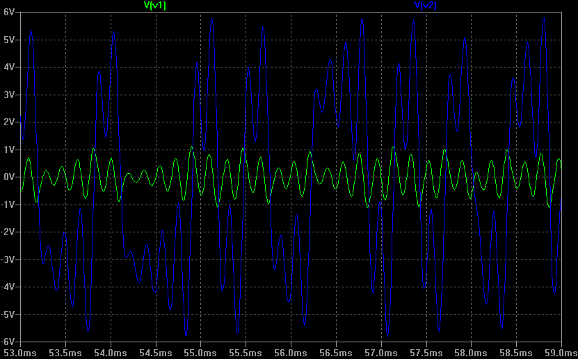
A transient simulation to 1/10th of a second gives the following waveforms for V1 and V2:


From up here, voltage V2 (blue) seems to be bouncing around two different DC levels at the same time!

A closer zoom on the waveforms shows some detail:


And if we change the x-axis to be V2 and the y-axis to V1, we get the beautiful double scroll plot:


I also ran an FFT for the signals, to see what kind of frequencies are involved:


Hmm, seems like it's audible... and so I couldn't stop there. I wanted to hear what it sounds like, so I made a simulation which outputs .WAV files.

Since LTSpice IV clips WAV outputs with an amplitude over 1V, I had to attenuate the two signals with voltage dividers. Here's the LTSpice circuit I used:

LTSpice simulation with WAV output!

If you want to simulate this one yourself, download the LTSpice project here.

The simulation for 10 seconds of audio took some time with my settings, and generated 500MB of raw data. Looking at it now, the time step (0.1ms) is lower than the sampling time... You might want to simulate with approximately 1/44100 time step, but that will produce even more data.

After all this, I could finally listen to the horrible screeching noise of chaos.

And so can you: The signal V1 (.wav) is more high-pitched, while the V2 (.wav) has lower frequencies in it's spectrum (like you can see from the FFT).

What it sounds like is noise, and a very annoying kind of noise.

I don't know yet how changing the value of R6 realtime will affect the sound. For that I would need to build the circuit and try it. With low values of R6, the circuit oscillates with a constant frequency. It would be neat to hear the moments at the edge of chaos. So I'll be probably building this one sometime. If someone has already built it, go ahead and post a comment!

Tuesday, September 13, 2011

Portable speaker for MP3 player

I made this portable speaker in the summer. It mixes the stereo input into a mono signal, which is then amplified. It's powered by a six pack of AA batteries. The batteries are held in an external battery pack, so they are easy to change on the fly, without the need of a screwdriver.

Completed speaker pumpin' out some bass

I was going to a cabin with the guys to celebrate juhannus (midsummer) the next day, and there was going to be no electricity. Juhannus without music wasn't an option, and I'm not too impressed by the portable speakers available in stores (overpriced and shit sound). So I built my own blaster that evening.

The circuit is a modified version of the portable guitar amplifier I've built many times. I found the original circuit years ago from the great site Red circuit designs. The circuit is modified to have a simple stereo-to-mono mixer in the input, consisting of resistors R1 and R2. I chose 1k as their value, that should be enough to isolate the left and right channels from each other, since the headphone output on an MP3 player has a low impedance.

There is no volume control, instead I just use the volume control of the MP3 player. If someone wants to add one, just replace R3 with a potentiometer and connect "In+" of the TDA7052 to the middle pin of the potentiometer...

Schematic of the amplifier.

Going through my sizeable e-trash collection I found an old pairless computer speaker. It would get a new life soon.

The victim, a pairless computer speaker.
It was a left speaker, with just a speaker inside and an RCA jack on the back. I was going to use that as the power jack.

An RCA jack on the back was going to be the power input.

I took the metal leg off to access the screws and opened the case. Next I cut the wires off the speaker. There was some foam padding inside, which I removed for a while.

Case opened and wires cut.

I soldered all the amplifier circuit on a small piece of stripboard and then the speaker and the jacks. A single screw hole in the back of the case was used to fasten the thing there.

The amplifier circuit board is fastened to the wall with a screw.

I glued some mouse pad pieces to the most critical places to ensure there's no unwanted vibrations. To top it off I put back the original foam padding.

Some pieces of old mouse pads ensure the wires don't vibrate around.

I put also the original foam padding back to further eliminate vibrations.

Here is the backside of the finished speaker. I sticked an inspirational sticker on the back. The RCA jack on the left is for power and the 3.5mm jack is a stereo line input.

Connectors on the back.

I used some part of an old projector as a vise when gluing the battery pack together. Very handy. Another gem saved from the trash.

Gluing the battery pack together...

The power packs are also 100% recycled: the battery holders and the piece of RCA wire were also found in e-trash.

Finished test battery pack, with random AA's I had at hand.

The speaker was a hit in Juhannus and got very good feedback from it's bassy and clean sound. Just have enough batteries with you - it ate 3 six-packs of AAs during the 3-day trip and would have eaten even more. Of course, the speaker was on all the time. When the batteries are running low the sound starts to get distorted but turning down the volume a bit helps. This way you can also extend the battery life a bit.

That's all folks!

Links
Red free circuit designs -  Mini Portable Guitar Amplifier
My mini guitar amplifier build

Monday, June 20, 2011

Mini guitar amplifier

[EDIT: also check out TDA7052 portable speaker for MP3 players I made.]

I've been building this circuit again and again since 2006, when I first built it.

It's an extremely simple mini amplifier. It has a single TDA7052 amplifier IC, a couple capacitors and one resistor... The circuit is designed and documented by RED free circuit designs. The TDA7052 datasheet also shows a very similar application example.

There's no volume control. You can use your guitar's volume knob. With full volume, there's usually some distortion, especially when the battery starts to drain up. But the distortion actually sounds pretty cool.

I've used this thing also as a speaker for my MP3 player. I just wired the left channel to the input of this thing. Works fine, but don't expect much from the sound quality...

My first amplifier build looks like this.

I had found some very cool old telephone routing / answering machines from Philips and decided to use one as the case. They're wooden and feature some very cryptic buttons...

Neat case!

You can see there's plenty of room left in the case... Note also the old film container I used as the battery holder.

The downside with the case is that it's far from airtight and doesn't give the best bass response.

Once a friend tried to use a wall wart to power one of these. He got the polarity wrong and blew the TDA7052, leaving a crater in the chip. I was called to the rescue. I had luckily used an IC socket, so I could replace the chip without any soldering.

Poor TDA7052...

Friday, June 17, 2011

DIY analog sequencer from 2006

I just found a directory tree full of pictures of my old creations. There's many strange, forgotten instruments and sound samples. I'll post them from time to time.

Let's start from one of the craziest.

This one is a 4-channel, 10 step analog sequencer. I still have it around.

Now that's just crazy...
The idea started back when I was 18. I had this vision of creating a sequencer-based tremolo for the guitar. I got it after hearing the song Stüldt Håjt from Kingston Wall (youtube link), I couldn't help but think how cool a hardware effect like that would be to have around. Actually I didn't like the song all that much, I just couldn't help but think about the guitar effect.

It took me three years until I realized that I could finally do it. The device would be modular and I could use it also to trigger whatever else I wanted it to, like some toy synths or other shit.

Of course, now that I look at it, I could do it better, and would go definitely digital, with some fancy LCD screen, unlimited steps, and stuff like that. And still, it would be a breeze to create, compared to all that soldering I had to go through with this clicking analog beast.

The thing is powered by a 4066 decade counter that is clocked by a 555 timer. The circuit is very simple but all the switches took a fucking long time to solder. Everything is enclosed in the shell of some old toy computer my then-girlfriend gave for me to hack.

Here's a feature list I wrote back then:
- Selectable pattern size with min. 2 and max. 10 beats
- 4 channels:
    - 2 channels with two outputs each
    - 2 channels with two outputs each, one output being inverted
- 10 LED display
- Fine & coarse BPM knobs

I had my reasons to put inverted relay outputs (normally closed) there, I was hoping that when combining a normally opened and a normally closed relay output, I could maybe trigger some sounds on each beat. I never got around to test this, though... I don't think it even works because of the extremely small time it takes for the relay to switch.

For those asking, I don't have the full schematic anywhere. That is because I never made one. Back then, I was a bit unorganized in my DIY projects. Anyway, I have some bits and pieces of the schematic, and an old write-up of the whole project. If there's enough interest, I might do some research and eventually post instructions.

Well, here's pics I found of the creation process.

Internals of the sequencer. On the left is the main circuit board. On the right is the relay board and the RCA outputs.
I remember taking the RCA outputs from some old stereo amplifier I found in the trash... I still use a lot of recycled parts in my projects.

Here's the insides combined. There seems to be some little additional breakout board on the right.
A dark picture of the unfinished case.
Beginning of the soldering nightmare...

Still missing the beat size selection switches and the BPM knobs.

All done! It was a pain in the ass...
When making the device, I left no way to open the case without cutting the wires to the control panel. I drilled a hole in the case, put the wires through, left no extra and just soldered it all to place. That's why I can't even find out the exact schematic anymore...

The set-up to achieve a sequenced tremolo guitar effect.
The cone with the yellow "egg" is an input/output box, which takes the signal through and RCA plug to a relay, which is controlled by the sequencer. The signal is taken to the device on the right, which is a very simple guitar amplifier I built. The guitar amp circuit is enclosed in an OLD Phillips answering machine thingie.

And here's the real beef. It's a sample of me playing a guitar through the above set-up, just before taking that picture, somewhere in 2006. I just used some cheap 5€ dynamic microphone. If you listen closely, you can hear the relays clicking inside the sequencer.


I'm still very pleased to hear this effect, even though I really haven't used the device for almost anything after recording this 42 sec clip. Well, I have sequenced a (very shitty) toy synth with it, but I don't have any samples of that... Maybe I should make some.

Stay tuned...